Ready to Calculate
Fill out the parameters on the left and click calculate to generate the bend details and layout.
How to Use the Sheet Metal Bend Calculator
Choose millimetres or inches, then select the mode that matches the job. Enter dimensions exactly as labelled and use a K-factor taken from verified shop data, a suitable bend table, or a measured test bend. Calculate, review the flat-pattern or centreline-marking results, and use Copy Result or Print Result to keep a workshop record. Before production, form and measure a test piece using the intended material, tooling and process.
Single Bend
- Enter material thickness, quantity, inside bend radius, bend angle and K-factor.
- Enter flange lengths A and B using the same dimensional convention as the drawing.
- Calculate and review bend allowance, outside setback, bend deduction and flat length.
- Transfer the flat length to the blank, then verify the formed dimensions on a test piece.
Segmented Radius
- Enter thickness and choose inside radius, outside radius, inside diameter or outside diameter.
- Enter the target dimension, total bend angle and K-factor.
- Choose automatic maximum spacing or enter a manual number of bend lines.
- Calculate, then transfer the centreline-out marks symmetrically to the sheet.
Single Bend Flat Pattern
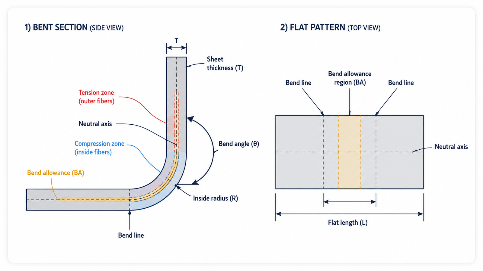
A flat pattern is the blank length before forming. The bend zone cannot be treated as a sharp corner because material follows a developed path around the bend. Fibres near the inside compress, fibres near the outside stretch, and a neutral axis between them is treated as retaining its original length.
Material thickness, inside radius, bend angle and K-factor establish that neutral-axis path. Flange A and flange B are the two straight leg dimensions. This calculator uses bend allowance for the neutral-axis arc, outside setback for the distance from the theoretical sharp corner to the bend tangent, and bend deduction to convert the two flange dimensions into one cut length. Total flat length multiplies the per-piece length by quantity.
Single-Bend Anatomy
Formula Guide
The active calculator uses the following relationships. Angle θ is converted to radians before the single-bend calculations.
Neutral-axis offset = K × TK = K-factor; T = material thickness.
BA = θ × (R + K × T)BA = bend allowance; θ = bend angle in radians; R = inside radius.
OSSB = tan(θ ÷ 2) × (R + T)OSSB = outside setback.
BD = 2 × OSSB − BABD = bend deduction.
Flat length per piece = A + B − BDA and B are the entered flange lengths. Total flat length equals the per-piece length multiplied by quantity.
Neutral radius = IR + K×T; OR − (1−K)×T; ID÷2 + K×T; or OD÷2 − (1−K)×TThe expression used depends on the selected inside/outside radius or diameter dimension.
Developed arc = 2 × π × neutral radius × bend angle ÷ 360Automatic spaces = ceil(developed arc ÷ maximum spacing); bend lines = spaces + 1For manual layout, spaces equal entered bend lines minus one. Spacing equals developed arc divided by spaces, and angle per space equals total angle divided by spaces.
Formed Part to Flat Pattern
Worked Single-Bend Example
Metric inputs: thickness 2 mm, inside radius 3 mm, bend angle 90°, K-factor 0.33, flange A 50 mm, flange B 75 mm and quantity 2.
- Neutral-axis radius = 3 + (0.33 × 2) = 3.66 mm.
- Bend allowance = 1.570796 × 3.66 = 5.75 mm.
- Outside setback = tan(45°) × (3 + 2) = 5.00 mm.
- Bend deduction = (2 × 5.00) − 5.75 = 4.25 mm.
- Flat length per piece = 50 + 75 − 4.25 = 120.75 mm.
- Total flat length for two pieces = 241.50 mm.
For one part, mark or cut a 120.75 mm blank before forming. The calculated value is a starting point; compare the first formed piece with the drawing and update shop bend data when necessary.
Segmented Radius Bend Layout
Segmented bending, often called bump bending, approximates a curve with a sequence of small press-brake bends. It is different from producing a continuous rolled radius: the result consists of short facets whose appearance depends on line spacing, bend consistency and the real forming setup.
The calculator first converts the selected inside/outside radius or diameter to a neutral-line radius. It then develops the neutral arc. Automatic mode rounds the number of spaces upward so calculated spacing does not exceed the entered maximum; manual mode uses the selected number of bend lines. More, closer lines generally create a smoother approximation but require more operations. The angle per space is the total angle divided evenly across the spaces.
Centreline-out marks are generated symmetrically. An odd number of lines includes a centre bend line; an even number places the centre between two lines. This layout does not verify tooling, minimum flange, tonnage or machine capacity. Use the Plate Rolling Calculator for rolled plate development, the Cone Calculator for conical geometry and the Pipe Miter Calculator for pipe intersections.
Rolled Radius and Segmented Bend
Centreline-Out Marking Layout
Worked Segmented-Radius Example
Inputs: 3 mm material, inside radius 250 mm, 90° bend, K-factor 0.50, automatic method and 50 mm maximum spacing.
- Neutral radius = 250 + (0.50 × 3) = 251.50 mm.
- Developed arc = 2 × π × 251.50 × 90 ÷ 360 = 395.06 mm.
- Spaces = ceil(395.06 ÷ 50) = 8; bend lines = 9.
- Actual spacing = 395.06 ÷ 8 = 49.38 mm.
- Bend angle per space = 90 ÷ 8 = 11.25°.
- Centreline-out marks are 0, then approximately ±49.38, ±98.77, ±148.15 and ±197.53 mm.
Mark the blank centreline first, measure the listed offsets left and right, and keep the sequence and bend direction consistent while forming. The calculator displays left and right marking lists separately.
Understanding K-Factor
K-factor expresses the neutral-axis location as a fraction of material thickness measured from the inside face. It is an input assumption, not a universal material constant. Material grade and thickness, tensile behaviour, bend method, tooling, die opening, inside radius, grain direction and shop process can all affect the developed result.
Prefer a proven bend table, the machine or CAD setup used by the shop, or a measured test bend. Even a small K-factor change alters bend allowance and therefore blank length. The default value is only a starting input and must not be treated as correct for every job.
Practical Workshop Checks
- Confirm actual thickness, not only nominal gauge.
- Confirm whether dimensions are inside or outside.
- Confirm the drawing's bend-angle convention.
- Use the intended tooling and forming method.
- Check material grade and grain direction.
- Allow for springback in the real setup.
- Verify the radius is producible with available tooling.
- Check minimum flange and bend relief separately.
- Check machine and tooling capacity separately.
- Measure a test coupon or first-off part.
Assumptions and Limitations
This is a planning and layout calculator. It uses the entered thickness, dimension type, radius or diameter, angle, K-factor, flange lengths, quantity and segmented-spacing method. It does not independently verify material-batch behaviour, springback compensation, tooling selection, die opening, punch radius, bottoming or coining behaviour, press-brake tonnage, minimum flange length, bend relief, grain-direction cracking risk, machine deflection, crowning, complex multi-bend sequence interaction, tolerance stack-up or manufacturer-specific bend tables.
Safety Note
Press brakes and hand-forming work can create crushing, pinch-point and sharp-edge hazards. Use trained operators, follow the machine and tooling manufacturers' instructions, keep safeguarding in place, keep hands out of the point of operation, use appropriate handling methods and PPE, and complete required workplace risk controls. A layout calculation does not make a forming operation safe.
Technical References
Terminology and safety guidance were checked against authoritative references:
Frequently Asked Questions
Calculation method, worked example and reference
What this calculator does and formula: Bend allowance BA = θ(R+K×T), where θ is radians, R inside radius, T thickness and K the neutral-axis factor.
Variables and units: Enter values in the units named by the controls. The calculator converts through its internal base unit or applies the displayed geometric or financial relationship before rounding the presented result.
Verified worked example: For 90°, R=2 mm, T=1 mm and K=0.33, BA = 1.570796×2.33 = 3.660 mm.
Result interpretation, assumptions and practical limits: K-factor, tooling, grain, springback and deduction must be proven with the material and press-brake setup before production.
Professional check: Treat the result as a planning estimate. Where safety, regulated work, contracts or significant money are involved, verify inputs and the result with the governing standard, manufacturer data and an appropriately qualified professional.
Authoritative reference
Bend Allowance & Flat Pattern Guide
Use this technical guide to identify the main bend variables and understand how a formed sheet-metal bend relates to its developed flat pattern.