Steel Weight Calculator
Estimate steel plate, pipe and section weight.
View CalculatorSmart tools for better decisions
Calculate flange PCD, bolt circle hole positions, angle step, chord distance and X/Y coordinates for drilling and fabrication layouts.
Input the Pitch Circle Diameter (PCD) and number of holes to generate calculated X and Y coordinates for layout and verification.
A Flange PCD (Pitch Circle Diameter) or Bolt Circle Calculator is an essential tool for machinists, fabricators, and engineers. It calculates the exact positions of bolt holes arranged in a circular pattern on a flange, wheel hub, or cover plate.
Instead of manually calculating complex trigonometry, this tool instantly provides the X and Y coordinates needed to program a CNC machine or to dial in positions on a manual mill using a Digital Readout (DRO). It also provides the chord distance, which is crucial for verifying the layout with calipers before drilling.
Generating a bolt circle layout is straightforward:
PCD stands for Pitch Circle Diameter. It is the diameter of the imaginary circle that passes exactly through the center of all the bolt holes on a flange.
Knowing the PCD is critical because it ensures that mating flanges will align perfectly. If the PCD is off by even a fraction of a millimeter, the bolts will not pass through both flanges.
The calculator uses standard trigonometric functions (sine and cosine) to convert polar coordinates (radius and angle) into Cartesian coordinates (X and Y).
The X coordinate is found by multiplying the pitch radius by the cosine of the hole's angle. The Y coordinate is found by multiplying the pitch radius by the sine of the hole's angle. These values are then added to the center datum coordinates.
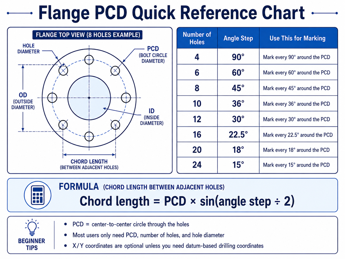
The angle step is the angular distance between the centers of two adjacent holes. It is calculated by dividing a full circle (360 degrees) by the number of holes.
The chord distance is the straight-line measurement between two adjacent hole centers. It is calculated using the pitch radius and the angle step.
Let's calculate a standard 8-hole flange with a PCD of 200mm and a Starting Angle of 0°.
Avoid these costly errors when laying out and drilling flanges in the workshop:
Confusing PCD with Outer Diameter: The PCD is always smaller than the outer diameter of the flange. Do not use the flange OD as your bolt circle diameter.
Incorrect starting angle: Many standard flanges (like ANSI or DIN) require holes to "straddle the centerline". This means the first hole is not at 0°, but offset by half the angle step.
Not verifying with chord distance: Always use calipers to check the chord distance between your center-punched marks before drilling. This catches math or DRO entry errors early.
Ignoring datum shifts: If your part is clamped such that the center of the flange is not at X0 Y0 on your machine, you must enter the correct Centre X and Y offsets into the calculator.
Estimate steel plate, pipe and section weight.
View CalculatorCalculate pipe cut angles and marking references.
View CalculatorCalculate bend allowance and developed sheet length.
View CalculatorDevelop full and truncated cone patterns.
View CalculatorThe coordinate table uses the flange centre as its datum before applying entered X/Y offsets. Zero degrees lies on positive X at the 3 o’clock position and positive angles advance counter-clockwise in the displayed Cartesian coordinate system. Mathematical coordinates do not guarantee machining accuracy; verify the drawing, flange standard, datum, tolerance, setup and chord before drilling.
Use the applicable manufacturer instructions, approved drawings and site procedures together with these primary safety references.
What this calculator does and formula: For n equally spaced holes on pitch-circle diameter D, adjacent chord spacing c = D×sin(π/n). Hole coordinates use radius D/2 with sine and cosine.
Variables and units: Enter values in the units named by the controls. The calculator converts through its internal base unit or applies the displayed geometric or financial relationship before rounding the presented result.
Verified worked example: For D = 200 mm and n = 8, adjacent chord spacing is 200×sin(22.5°) = 76.5367 mm.
Result interpretation, assumptions and practical limits: This is layout geometry only. Verify flange standard, hole diameter, orientation, gasket, pressure class and machining tolerances from the governing drawing.
Professional check: Treat the result as a planning estimate. Where safety, regulated work, contracts or significant money are involved, verify inputs and the result with the governing standard, manufacturer data and an appropriately qualified professional.
Use this guide to identify the flange outside diameter, inner bore, pitch circle diameter, bolt-hole diameter, angle step and straight-line chord distance between adjacent hole centres.
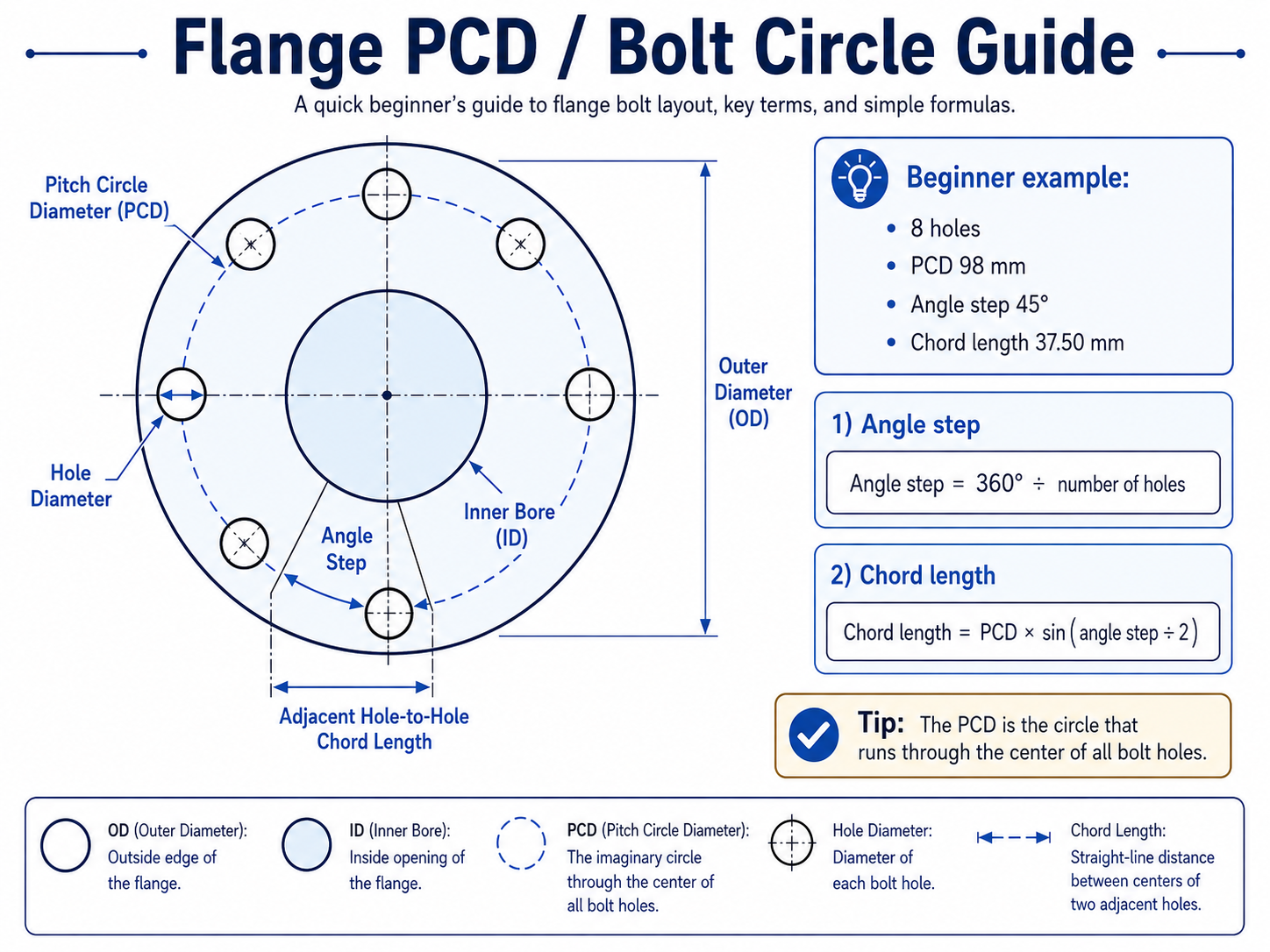
For equally spaced holes, divide 360° by the number of holes to find the angle between adjacent hole centres. The chart shows common hole counts and their angle steps.