Steel Weight Calculator
Estimate the weight of pipe, tube and fabricated steel sections.
View CalculatorSmart tools for better decisions
Calculate simple miter geometry, multi-piece pipe bend layouts and saddle or fish-mouth marking coordinates for fabrication work.
Select your calculation mode, input the pipe diameter and required angles, then click calculate to generate the cut dimensions.
This pipe miter calculator provides geometric reference values for simple miter joints, multi-piece miter bends and round-pipe saddle or fish-mouth intersections. Depending on the selected mode, it calculates cut angles, marking offsets, bend geometry, piece schedules and branch-pipe profile coordinates.
The calculator is intended for fabrication planning in plumbing, HVAC, structural steel work, exhaust fabrication, handrails and similar pipe or tube projects. Accurate layout can reduce trial fitting, grinding and material waste, but final fit-up still depends on the actual pipe, cutting process and fabrication tolerances.
It provides calculated angles and contour reference coordinates that can reduce layout time for supported modes. Verify the drawing, cutting method, tolerances and fit-up before fabrication.
This layout tool is designed for professionals and tradespeople working with metal, PVC, or composite pipes:
For a simple miter joint, the core formula is Miter Angle = Joint Angle / 2. The saw cut must exactly bisect the desired angle.
For saddle or fish-mouth joints, the calculator uses the main-pipe diameter, branch-pipe diameter and branch angle to generate reference cut depths at equally spaced positions around the branch circumference. Increasing the number of marking points gives more reference coordinates for transferring the calculated profile.
Accurate miter and saddle layout can reduce excessive gaps, unnecessary grinding and material rework. The calculated geometry is still only one part of fabrication; bevel preparation, root opening, alignment and welding requirements must come from the applicable drawing and procedure.
Let's calculate the miter for joining two 4-inch (101.6mm) pipes to form a perfect 45-degree angle.
Fabrication Implications: Set your cold saw or band saw to exactly 22.5°. If cutting manually, a 319.19 mm wrap-around reference can be used to establish a square circumferential baseline on a 101.6 mm OD pipe before transferring the required cut geometry. Prepare the joint only as required by the approved drawing, fabrication code and welding procedure.
Confusing miter angle with pipe angle
Setting the saw to 90 degrees to make a 90-degree corner. You must set the saw to 45 degrees. The miter angle is half the joint angle.
Using the wrong pipe diameter
Using nominal pipe size (e.g., 2") instead of actual Outside Diameter (OD, which is 2.375" or 60.3mm for a 2" pipe). Marking coordinates will be entirely wrong.
Not accounting for pipe wall thickness
Templates give you the exterior cut line. Thick-walled pipe must be beveled heavily on the inside curve of the fish-mouth to fit flush against the main pipe.
Forgetting pipe expansion during welding
Assuming one universal root opening or shrinkage allowance. Use the drawing and approved welding procedure for the required preparation and dimensional allowance.
Estimate the weight of pipe, tube and fabricated steel sections.
View CalculatorEstimate welding and preparation consumables for pipe joints.
View CalculatorCalculate bolt-circle spacing and flange-hole coordinates.
View CalculatorCalculate bend allowance and developed sheet length for fabrication.
View CalculatorCalculated angles and marking depths are geometric references. Confirm physical piece and joint counts, drawing tolerances, cutting kerf, bevel, root opening, ovality and fit-up requirements before fabrication. Welding preparation must follow the approved drawing, process and welding procedure rather than a universal bevel or root-gap rule.
Enter a positive joint or total bend angle below 180 degrees. The calculator now rejects 180 degrees and larger values for these modes.
Angular divisions are the number of equal direction changes in the multi-piece bend. The calculator treats n angular divisions as n miter joints and n + 1 straight pipe pieces for the tangent-ended bend layout shown in the results.
Use the drawing, applicable fabrication code and approved welding procedure. Kerf, bevel, root opening, ovality and alignment requirements are process-specific.
Use the applicable manufacturer instructions, approved drawings and site procedures together with these primary safety references.
Simple Miter: For a symmetric two-pipe miter joint, the cut angle on each mating pipe end is half the required direction change. If the joint angle is θ, the miter cut angle is θ ÷ 2. The calculator also uses the pipe radius to calculate the centre-to-edge marking offset and the total long-to-short difference across the pipe OD.
Simple-miter marking formulas: Pipe radius r = OD ÷ 2. Centre-to-edge offset = r × tan(θ ÷ 2). Long-to-short difference = OD × tan(θ ÷ 2). These are ideal geometric dimensions before cutting-process and weld-preparation allowances.
Multi-Piece Miter Bend: The total bend angle is divided into equal angular changes. If there are n angular divisions, the direction change per joint is Total Bend Angle ÷ n and the miter cut angle on each mating face is half that value. The calculator treats n angular divisions as n miter joints and n + 1 straight pipe pieces.
Multi-piece radius geometry: When a centreline bend radius is entered, the calculator provides theoretical centreline arc length, arc length per division, straight chord per division, tangent-based end and intermediate piece dimensions, inside/outside reference lengths and a piece-by-piece cutting schedule. The arc dimension is a geometric reference and must not be confused with a straight physical cut length.
Pipe Saddle / Fish-Mouth: Enter the main-pipe OD, branch-pipe OD, branch angle and number of marking points. The calculator divides the branch circumference into equal positions and returns the angle around the branch, distance around the branch and reference cut depth for each point. It also plots the calculated profile as an unwrapped visual reference.
How to use saddle results: Establish Point 1 / 0° on a straight axial reference line along the branch pipe. Measure around the branch using the calculated distances, transfer the corresponding cut depths from the same axial reference, then join the points with a smooth curve. The on-screen profile is a visual reference and is not a 1:1 printable cutting template.
Worked example — Simple Miter: A 100 mm OD pipe forming a 90° symmetric joint requires a 45° miter cut on each pipe end. The pipe radius is 50 mm, giving a 50 mm centre-to-edge offset and a 100 mm long-to-short difference in ideal geometry.
Worked example — Multi-Piece: A 90° bend with 3 angular divisions produces three 30° direction changes, three miter joints and four straight pipe pieces. Each mating face uses a 15° miter cut. With a 1000 mm centreline bend radius, the calculator can then generate the related arc, chord and fabrication-piece reference dimensions.
Fabrication limits: Results are based on ideal geometric OD relationships. Actual fabrication must separately account for kerf, bevel, root opening, wall thickness, ovality, alignment, welding procedure, fit-up tolerance and any drawing-specific allowance. Pressure piping and other regulated work must follow the applicable design code, approved fabrication drawing and welding procedure.
Use this workshop reference to understand simple miter joints, multi-piece bend divisions, cut angles, centreline geometry, layout ordinates and practical fabrication checks.
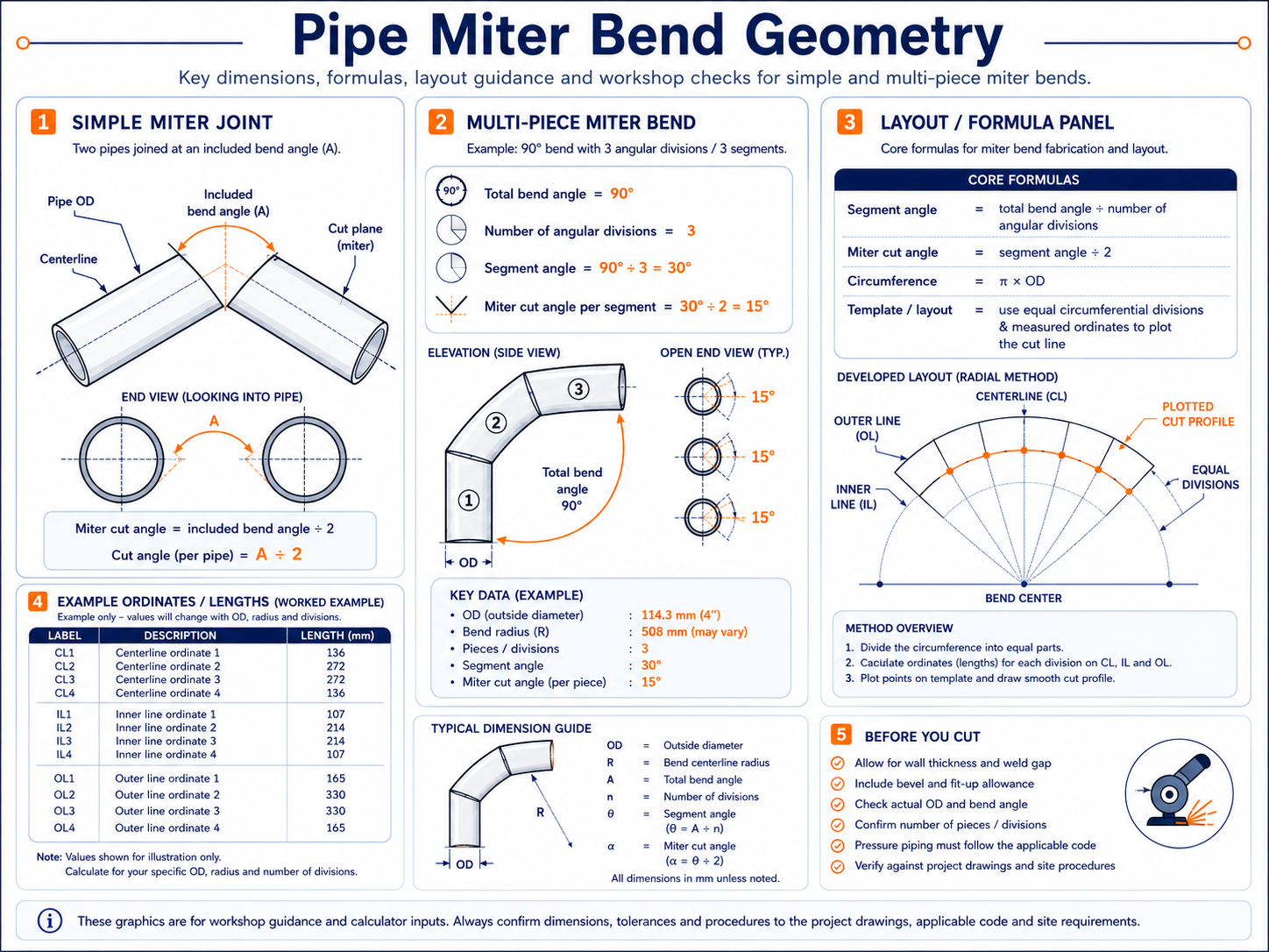
Diagram values are illustrative. Calculate the actual pipe OD, bend angle, number of divisions and bend radius for the job, then confirm allowances, fit-up and applicable piping requirements before fabrication.