Cable Parameters
Enter your load parameters
Select your calculation mode, input the load details, and cable length to generate voltage drop estimates.
What this calculator does
This cable size and voltage drop calculator determines the appropriate cable cross-section based on load current and distance. It calculates the voltage drop over a cable run to ensure safe installations that meet electrical codes (like NEC or IEC).
By accurately sizing cables, it prevents overheating, fire hazards, and equipment damage caused by undervoltage. It is widely used in residential, commercial, and industrial settings, as well as for solar installations, EV charging stations, and long-distance power distribution.
The tool helps you balance safety, efficiency, and cost by finding the smallest cable size that safely meets voltage drop limits.
Who should use it
This tool is designed for professionals who need accurate electrical estimates:
- Licensed Electricians: For sizing cables for new circuits and subpanels.
- Electrical Engineers: To verify designs and ensure code compliance.
- Solar Installers: For sizing DC cables from panels to inverters to minimize power loss.
- Facility Managers: To plan equipment upgrades and power distribution.
- Industrial Electricians: For sizing long motor runs in factories.
- Code Inspectors: To quickly verify field installations.
Formula or calculation method
The core formula for single-phase voltage drop is: Voltage Drop = (2 × Load Current × Cable Length × Resistance) / 1000. For three-phase, the multiplier is √3 instead of 2.
Cable resistance depends on the material (copper has lower resistance than aluminum) and the cross-sectional area. Standard voltage drop limits are typically 3% for branch circuits and 5% for main feeders.
Voltage drop matters because excessive drop causes equipment (especially motors) to draw more current, overheat, and fail prematurely. It also represents wasted energy (I²R loss) heating up the cable. Proper sizing prevents these failures and ensures efficiency.
Practical worked example
Let's calculate the cable size for a 30A single-phase load located 50m away from the panel, using copper cable and a maximum 3% voltage drop on a 230V supply.
- Step 1: Test a 4mm² cable.
Resistance is approx 4.61 Ω/km. - Step 2: Calculate voltage drop.
Vd = (2 × 30A × 50m × 4.61) / 1000 = 13.83V - Step 3: Calculate percentage.
(13.83V / 230V) × 100 = 6.01% (Fails the 3% limit) - Step 4: Test a 10mm² cable.
Resistance is approx 1.83 Ω/km. Vd = 5.49V (2.38%). Passes!
Safety Implications: Using the 4mm² cable would cause a 6% drop, potentially damaging the equipment and causing the cable to run hot. The 10mm² cable ensures safe, efficient operation. Always verify the chosen size against ampacity tables for your specific installation method.
Common mistakes to avoid
Using undersized cable
Sizing only for ampacity and ignoring voltage drop on long runs leads to overheating, fire risks, and equipment damage.
Confusing copper and aluminum
Aluminum has higher resistance. Using copper tables for aluminum wire will result in severe undersizing.
Not accounting for round trip
In single-phase circuits, current travels down the live wire and back the neutral. The formula must account for both lengths.
Ignoring temperature derating
Cables running through hot attics or bundled together cannot carry as much current. Always apply code derating factors.
Frequently Asked Questions
Safety verification, formula and limits
Formula: load current is P/(V×PF×η) for single phase and P/(√3×V×PF×η) for balanced three phase. Voltage drop is 2LIR for single phase and √3LIR for three phase, using one-way length L and conductor resistance R in Ω/m. The result checks voltage drop only; it does not prove ampacity, fault-loop impedance, protection, insulation, grouping or temperature compliance.
Verified example: 3 kW, 230 V, PF 1.0 and 100% efficiency gives 13.04 A. A 4 mm² copper conductor using the calculator resistance of 4.61 Ω/km over 30 m gives 3.61 V drop, or 1.57%, and 226.39 V at the load.
Safety: select conductors and protective devices from the locally adopted wiring rules and manufacturer data. A licensed electrician must verify installation method, ambient and grouping corrections, short-circuit withstand, disconnection time and terminations—especially for aluminium conductors.
Authoritative references
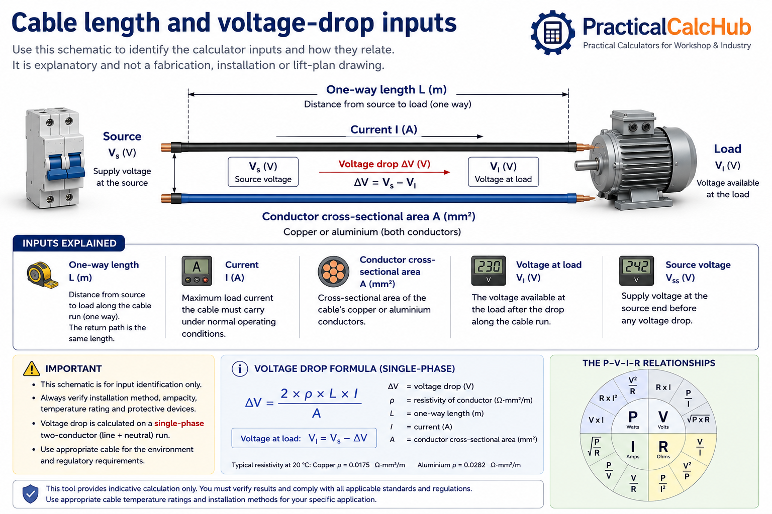
Cable length and voltage-drop inputs
Use this guide to identify the calculator inputs and understand how cable length, current, conductor area and source voltage affect voltage at the load. The illustration is explanatory and is not an installation drawing.