Ready to Calculate
Add your electrical loads and configure your supply details on the left, then click calculate to see your estimated demand and current.
What this calculator does
This electrical load calculator estimates connected load and demand load for buildings, workshops and similar installations. It combines the entered loads with user-selected demand factors and power factors to provide a practical planning estimate of electrical demand and current.
It can support early-stage planning for panel capacity, supply requirements and load distribution. Demand factors help represent that not every connected load is expected to operate at full power at the same time.
It can be used for preliminary residential, commercial and workshop load planning. Final service capacity, breaker ratings, conductor sizes, protection, phase balancing and compliance requirements must be verified for the actual installation.
Who should use it
This calculation tool is designed for electrical professionals and planners:
- Licensed Electricians: To estimate connected and demand loads during early planning.
- Electrical Engineers: For preliminary load scheduling and panel design.
- Architects & Construction Contractors: To estimate incoming utility service requirements early in the project.
- Facility Managers: To review the estimated load impact of proposed equipment upgrades.
- Energy Auditors: To compare estimated connected and demand loads during preliminary reviews.
- Project Reviewers: To review preliminary load assumptions before detailed electrical design.
Formula or calculation method
The fundamental principle is: Total Load = Sum of all connected loads (lighting, HVAC, sockets, machinery).
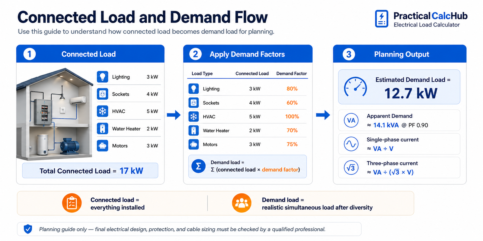
For loads with individual demand factors, the planning method is: Demand Load = Σ(Connected Load × Demand Factor). Each demand factor represents the expected proportion of that connected load included in the simultaneous-demand estimate.
Using realistic demand factors can provide a more useful planning estimate than simply adding every connected load at full rating. Demand factors should not be guessed; use values appropriate to the installation and applicable electrical requirements.
Practical worked example
Let's calculate the load for a small commercial office with the following equipment:
- • Lighting (5kW total): 5kW × 80% demand factor = 4.0kW
- • HVAC (8kW total): 8kW × 100% demand factor = 8.0kW
- • Computers (3kW total): 3kW × 70% demand factor = 2.1kW
- • Kitchen/Stove (4kW total): 4kW × 80% demand factor = 3.2kW
Connected Load: 5 + 8 + 3 + 4 = 20.0 kW.
Demand Load: 4.0 + 8.0 + 2.1 + 3.2 = 17.3 kW.
Planning Current Example: A 17.3 kW demand load at unity power factor on a 230V single-phase supply corresponds to approximately 75.2 A. Applying a 20% planning margin gives approximately 90.3 A. This is a planning-current example only; final supply rating, protection and conductor sizing must be determined from the actual load schedule and applicable electrical requirements.
Common mistakes to avoid
Adding all loads without demand factors
Assuming 100% of equipment runs simultaneously massively oversizes the required electrical service, costing thousands in unnecessary copper and transformer upgrades.
Using wrong demand factors
Applying a 50% demand factor to heating/HVAC loads is dangerous. Heaters and air conditioners often run continuously at 100% capacity during extreme weather.
Forgetting future expansion
Sizing the main breaker exactly to the current load leaves no room for new equipment. Upgrading a main service later requires power outages and costly rewiring.
Not accounting for motor startup
Heavy motors pull 5-7x their running current on startup. The main service and breakers must absorb this brief surge without tripping.
Frequently Asked Questions
Related Calculators
Verified load method and safety limits
Formula: connected watts = watts × quantity. Demand watts = connected watts × demand factor. Apparent demand VA = demand watts ÷ power factor. Current is VA/V for single phase or VA/(√3V) for an assumed balanced three-phase supply; the selected planning margin is then added.
Verified example: the displayed office example totals 17.3 kW demand. At unity PF on 230 V single phase this is 75.22 A; adding 20% gives 90.26 A, agreeing with the stated approximately 90 A.
Safety: demand factors are planning inputs, not universal code allowances. A qualified electrical designer must apply the locally adopted load-calculation rules, phase allocation, continuous-load requirements, motor starting, neutral harmonics, protection and service limits. The result does not size conductors or breakers.
Authoritative references
Connected load and demand flow
Use this guide to understand how connected load becomes estimated demand load after demand factors are applied. It also shows how apparent demand and planning current relate to the final result. This is an explanatory planning guide, not a final electrical design.